
Spin transfer appears to be a promising tool for improving spintronics devices. Experiments that quantitatively access the magnitude of the spin transfer are required for a fundamental understanding of this phenomenon. By inductively measuring spin waves propagating along a permalloy strip subjected to a large electrical current, we observed a current-induced spin wave Doppler shift that we relate to the adiabatic spin transfer torque. Because spin waves provide a well-defined system for performing spin transfer, we anticipate that they could be used as an accurate probe of spin-polarized transport in various itinerant ferromagnets.
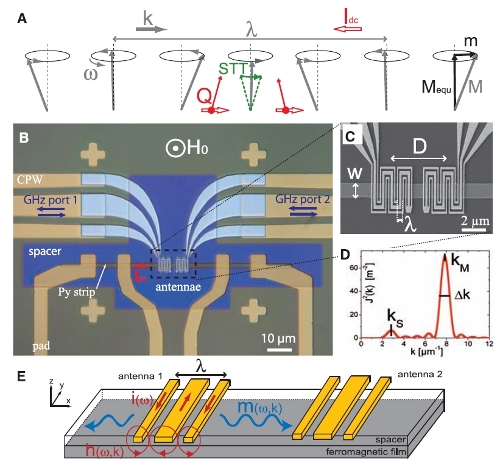
Principle of the spin wave measurements. (A) Sketch of a spin wave subjected to spin transfer torque (case of a spin wave propagating against the dc current – along the electron flow- with a spin polarization P > 0). The red arrows represent the flow of spin-polarized electrons (the spin current Q). (B) Optical micrograph of the device with a w = 2µm permalloy strip (t = 20 nm) and a pair of lamba = 0.8 µm antennae. ( C) Scanning electron micrograph of the central region. (D) Fourier transform of the microwave current density for the antenna shown in ( C). It was calculated by assuming a uniform current density across each branch of the meander. (E) Sketch of the operating principle of propagating spin wave spectroscopy.
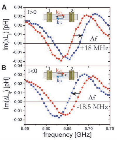
Influence of a dc current on the spin wave propagation. (A) Mutual inductance measurement in the presence of a I =+6mA dc current for the w=2µm, ![]() = 0.8 µm sample under
= 0.8 µm sample under ![]() = 1.029 T.
= 1.029 T. ![]() is shown as a red curve and corresponds to spin waves propagating from antenna 1 to antenna 2.
is shown as a red curve and corresponds to spin waves propagating from antenna 1 to antenna 2. ![]() is shown as a blue curve and corresponds to spin waves propagating from antenna 2 to antenna 1. The orientations of the spin wave wave vector and of the electron flow are shown in the inset. The measured frequency shift
is shown as a blue curve and corresponds to spin waves propagating from antenna 2 to antenna 1. The orientations of the spin wave wave vector and of the electron flow are shown in the inset. The measured frequency shift ![]() is indicated on the graph. For clarity, only the imaginary part and only the frequency range corresponding to the main peak (
is indicated on the graph. For clarity, only the imaginary part and only the frequency range corresponding to the main peak (![]() ) are shown. (B) Idem for I = –6 mA.
) are shown. (B) Idem for I = –6 mA.
References:
V. VLAMINCK, M. BAILLEUL ,
Spin-wave transduction at the submicrometer scale : experiment and modelling,
Phys. Rev. B 81, 014425/1-13 (2010).
V. VLAMINCK, M. BAILLEUL,
Current-induced spin-wave Doppler shift ,
Science 322, 410-413 (2008).